Some of our products are built on a " DMX + Power over CAT5" system. This article explains about the system and why it may or may not be right for your display.
There are cases where RGB DMX controlled elements only require low levels of power. Examples might be flood lights, CoroStars or MegaBalls. In these cases, you often have a number of these elements, each which requires power and a DMX signal for control of the element. So, instead of running two cables - one for power and another for signal, it is possible to combine both the signal and power on the same cable. That "cable" could be any type of cable with atleast 4 conductors (two for power, two for DMX). So why use CAT5 cable?
-
Cost - CAT5 is just about the least expensive cable that can be found.
-
Avaiaiblity - CAT5 can be found everywhere.
-
Connectors - CAT5 already has many different types of spiltters and couplers and is the primary method used for nearly all controllers used in the Holiday Lighting arena.
-
Diversity - CAT5 cable can be found in every size (inches to hundreds of feet) and every color.
How does the DMX + Power over CAT5 process work?
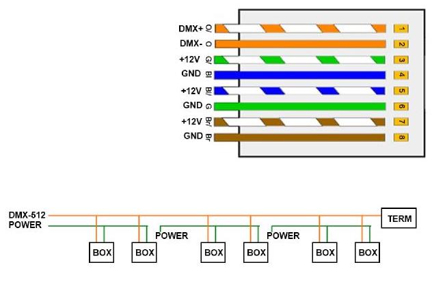
Within a CAT5 cable, there are eight wires. Each of the wires is able to handle about .5 amps of power. How much power exactly varies (see below). Basicly what happens is that two wires (the orange pair in nearly all cases using the T568B standard) are used to carry the DMX signal over the CAT5 cable. That leaves the remaining six wires free to run power. To use the six wires as just "two" wires, we then pair up the wires so that three of the conductors in the CAT5 form the negative wire and three form the positive, thus allowing additional current carrying capicity. The wiring standard is as follows:
|
Wire Function
|
CAT5 Pin
(T568B)
|
Wire Color
(T568B)
| 3 Channel DMX
Controller #27
|
|
DMX Signal / RS-485 Positive
|
1
|
White / Orange Stripe
| Data (Red) DMX + |
|
DMX Signal / RS-485 Negative
|
2
|
Solid Orange
| Data (Green) DMX - |
|
Power Positive +
|
3
|
White / Green Stripe
| Power (Red) Power + |
|
Power Negative -
|
4
|
Solid Blue
| Power (Black) Power - |
|
Power Positive +
|
5
|
White / Blue Stripe
| Power (Red) Power + |
|
Power Negative -
|
6
|
Solid Green
| Power (Black) Power - |
|
Power Positive +
|
7
|
White / Brown Stripe
| Power (Red) Power + |
|
Power Negative -
|
8
|
Solid Brown
| Power (Black) Power - |
You'll notice that this system is pretty easy to remember since each "solid" color is negative (black) and each striped color is positive (red).
How many items can I connect over CAT5 cable?
The number of items you can run over CAT5 depends on a variety of factors:
-
Length of CAT5 Cable - Just like when you add one garden hose to another garden hose and the pressure drops, the same thing occurs in wiring, including CAT5. So, as the distance of the cable increases, the more power is lost due to the distance travelled by the electrons. It's hard to determine exactly how much as each CAT5 cable is different (wire sizes, design, conductor metals) but usually it's safe to say if your length of cable is under 100 ft you should be fine. As your total length of cable grows, you will need to test to determine how much power is being lost due to the cable length.
-
The operating voltage of the devices - Higher voltage items (12v vs. 5v) will be less sensitive to drops in power consumption.
-
The current draw for each element connected to the cable - This is the most important factor. First you need to determine the power draw from the entire item - this includes the LEDs and controller. Usually you can make some general assumptions based on data from the vendor selling the controller and LEDs. For information on how to determine power draw, see our Knowledge Base.
Here is a simple diagram that explains the wiring and setup:
NOTE: The DMX + Power over CAT5 system is NOT to be confused with Power Over Ethernet or POE, which is a much higher voltage and is not compatible.
|